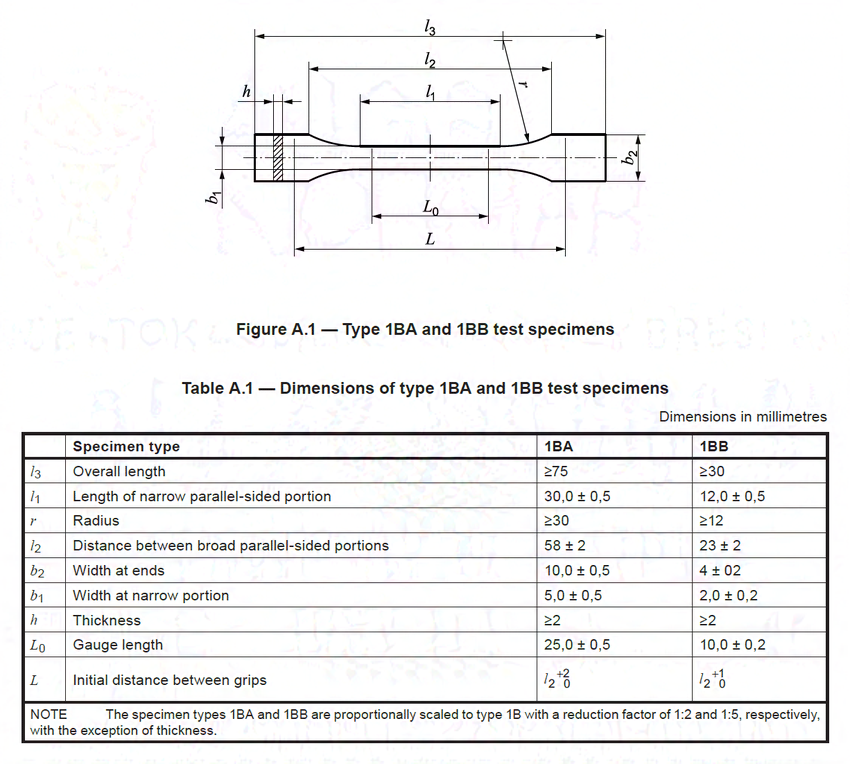
For this experiment I used ISO 1B test strips to measure the effect of carbon fiber reinforcement on traditional FDM 3D printer technology. Traditionally 3D printers place a single fiber using an advanced extrusion head and a filament spool to precisely place the fiber. These systems are complex and expensive, leading to a high cost. I chose to exchange the precision and accuracy for a DIY approach of placing the fibers by hand. This method has several challenges; however, it brings with it several benefits. I chose to place the fiber directly by hand into each layer. This has the benefit of being low cost, working on any 3D printer, and with a wide range of materials, or combination of several.
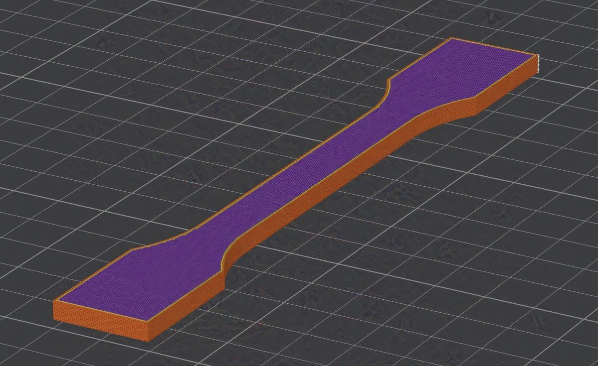
Immediately there are several challenges that need to be overcome: 1. The fibers need to be held to the print surface so that they do not catch on the nozzle of the printer. 2. The fibers need to be placed manually, which takes time. 3. The fibers need to be surrounded by a thermoplastic matrix.
To address the first issue, I ensured that the 3D printer placed several wall type layers outlining the geometry of the print layer. This effectively pins the fiber down and holds it to the part. In my initial prototyping I pulled fibers from a 45-45 weave and secured them to the build plate with masking tape. The layer would then print the part outline which fully pinned the fibers to the part. By pinning down the fibers, it became possible to place the fibers more reliably and without holding them by hand on the print bed for the duration of the print.
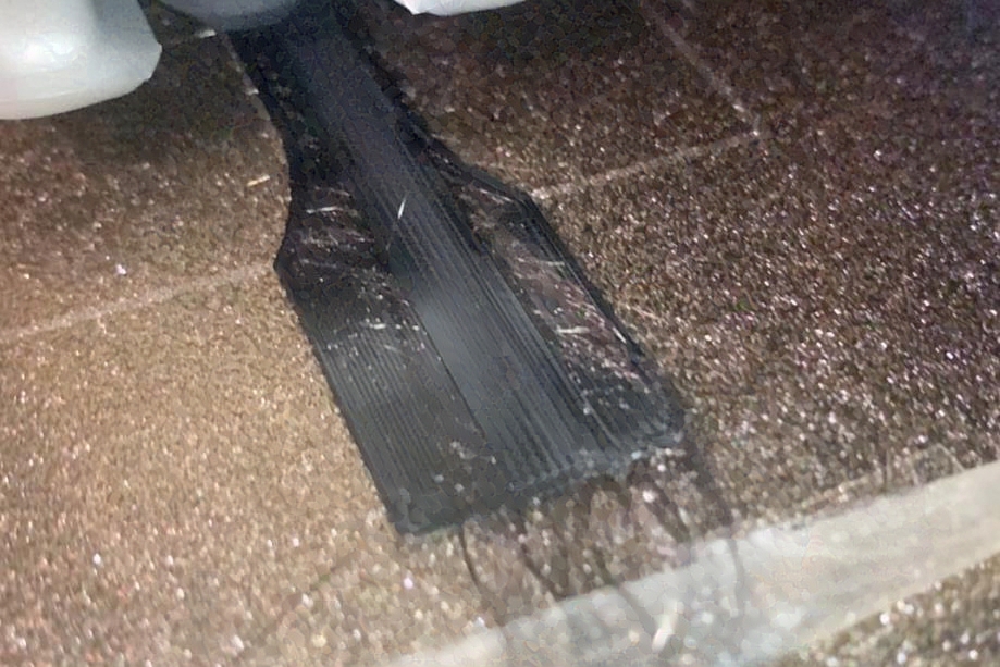
The third issue was that of matrix adhesion. Using a thick bundle of fiber proved to be impossible as the thermoplastic would only adhere to the fibers on the top layer of the bundle, allowing them to peel away with printhead forces. To solve this, I used smaller strands as well as pulled each strand into a loose mesh through which the thermoplastic could penetrate. This allowed space for proper adhesion and penetration of the plastic between the matrices.
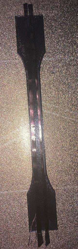
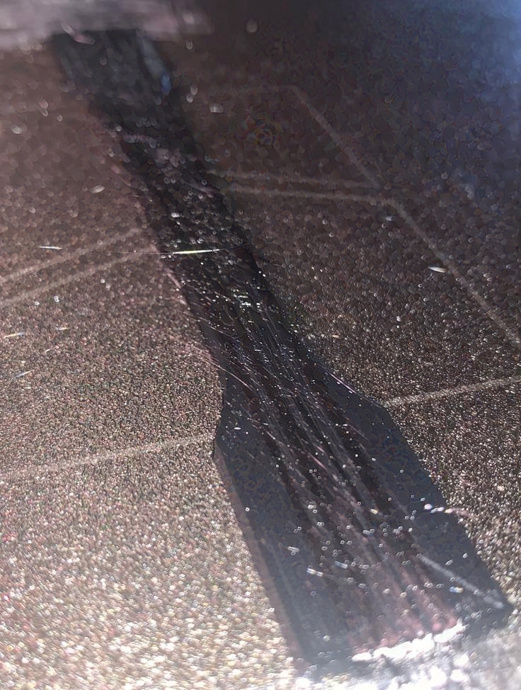
I also noticed that if the bundle of fibers was twisted, it would push the layer height upwards and prevent proper geometry at the next layers. A twisted bundle or strand is thicker than a flat bundle or mesh. When taking strands from a 45-45 weave of fiber, it is critical that the fibers are not grouped too tightly together to prevent proper adhesion. In an early test strip, I noticed that thick bundles created disconnects in the part, such that when bent, a void would open in the part. This was only determined after the samples were fabricated, so three test strips use the thick bundles.
Test Articles
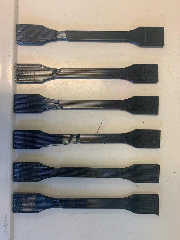
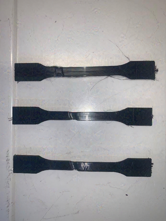
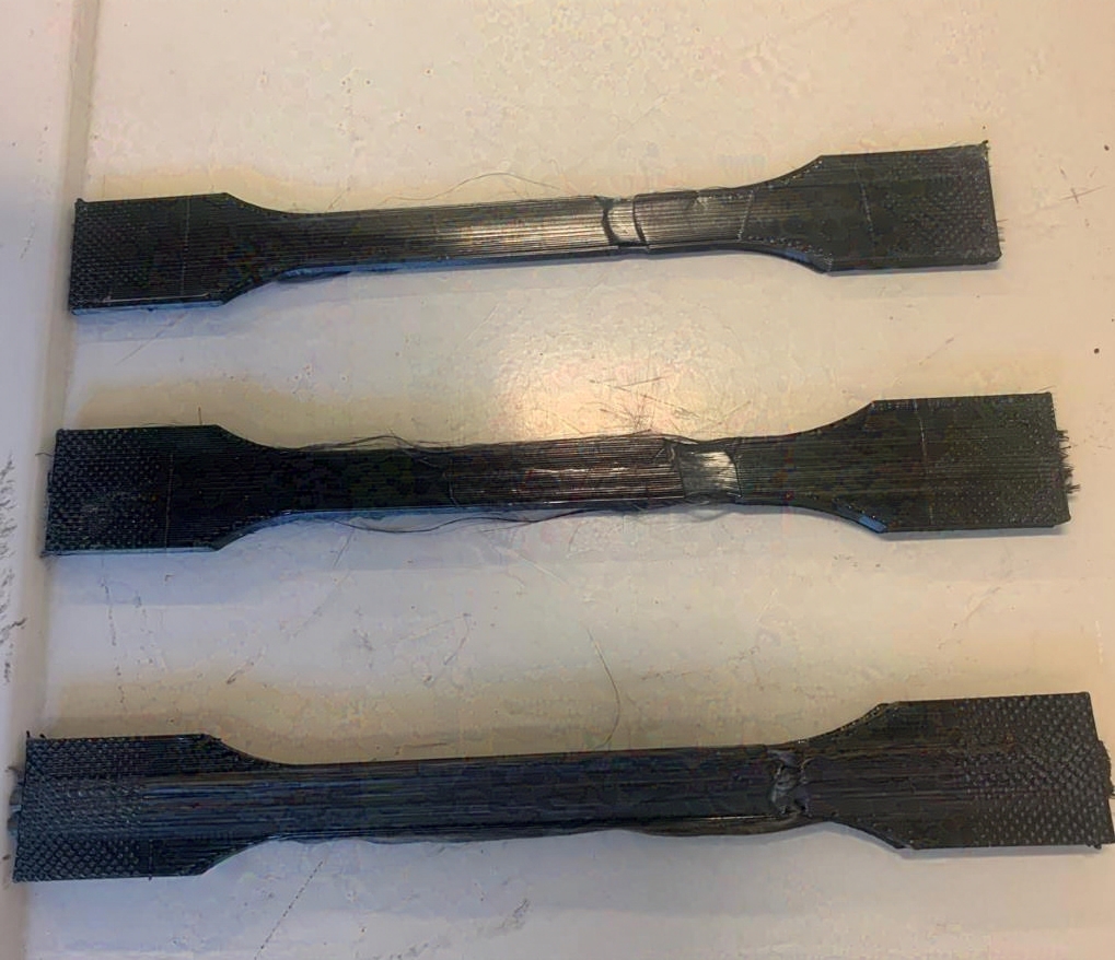
Several variations and methods for embedding the carbon fiber were used to create a total of 16 test articles. These test articles were tensile tested to determine their maximum load.
Results
Strength Analysis
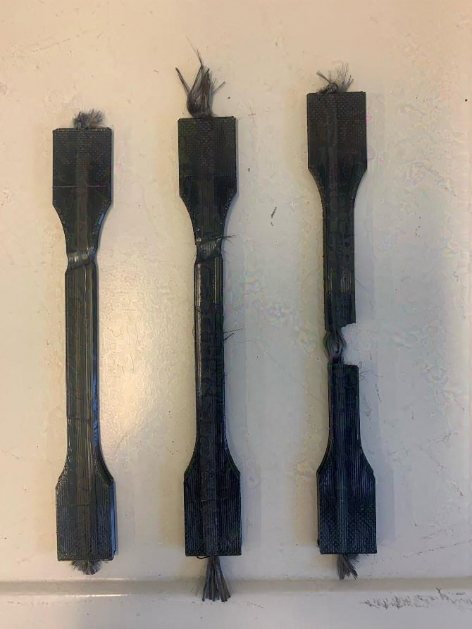
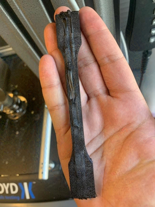
The strength of the seven layer test article was approximately 4 times greater than the standard unreinforced PET-G samples. Unfrotunately, my stress strain plots and data recorded was lost due to data corruption. The exact strength was less than the theoretical limit because of un-even bonding between fiber and PETG. My results showed a strong cooreleation between matrix bonding between layers and tensile strength.
Improvements
There are several methods for improvement of hand placed carbon fiber matrices on FDM printers that I will recommend. First, layer adhesion between the carbon matrices is the most important factor. To maximize this, a carbon matrix should have adequate spacing through which plastic may bond. A larger nozzle will allow for more material to be pushed through the matrices and bonded at one time. This larger nozzle will have a higher offset for extrusion, allowing it to pass over larger pieces of fiber which may add more strength.
One issue I ran into was the nozzle catching stray fibers and ripping the part from under the walls that were previously placed on the edges. Thicker layer heights would also create more smooth layers when placing with the existing matrix size. For all the designs, it took 2 layers of extrusion on top of the plastic before the layer had fully smoothed out. For thicker fibers and twisted fibers, there was a bump visible even from the outside of the test strip.
A premade matrix grid that could be placed or snapped over the part during a layer pause would also greatly improve the ease with which this method can be performed. This could be easily constructed in the same way that I am using walls in my current method.
Overall, this technique offers an accessible—though admittedly slow—way to improve the strength of thermoplastic FDM prints. More organized and prefabricated tools to assist in fiber placement could make this method competitive with the strength of dedicated carbon fiber 3D printers like the Markforged carbon printer.