This project was to build carbon fiber composite rotor blades to go with my collective pitch assembly to ultimately verify my Finite Element Analysis script I wrote to calculate the lift from a given rotor blade. While a blade with taper, camber, and a little twist would be more efficient, I chose a symmetric NACA 0012 foil with no twist or taper. This makes the resulting blade much easier to manufacture as well as qualify the symmetry and manufacturing process of the resulting blades.
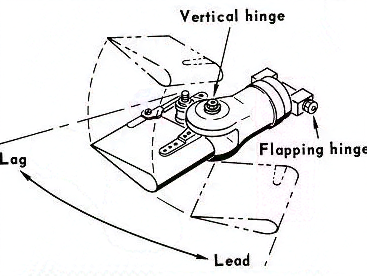
The fabrication method I chose was a wet layup with 3d printed mold core. A more professional manufacturing company might use some combination of die, bladder, or mold to create this kind of geometry. Often times you want a hollow part for weight savings, but helicopter blades actually benefit from higher mass. A heavier blade has more momentum and so it reduces the relative effect of the drag force to create a moment in the leading and lagging direction as the angle of attack of the collective pitch assembly is changed.
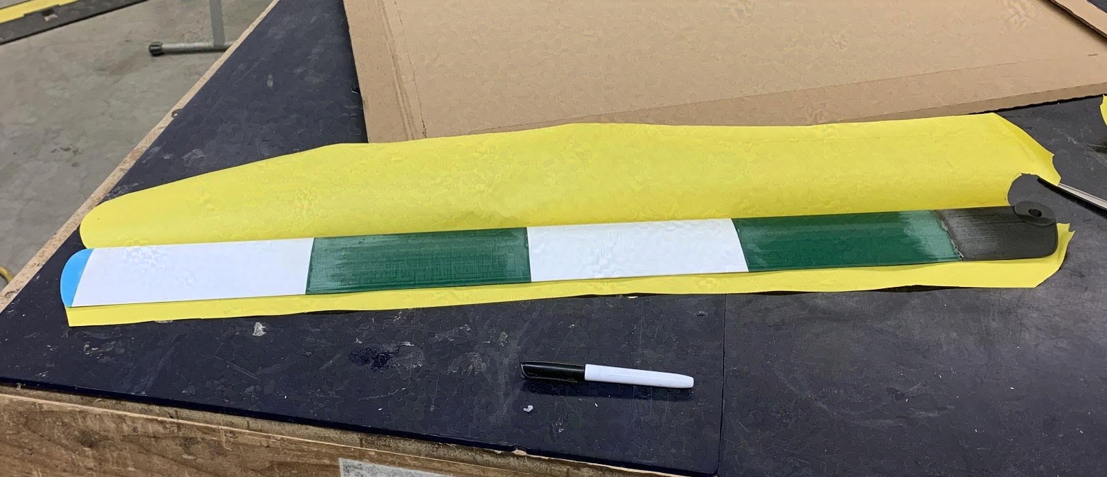
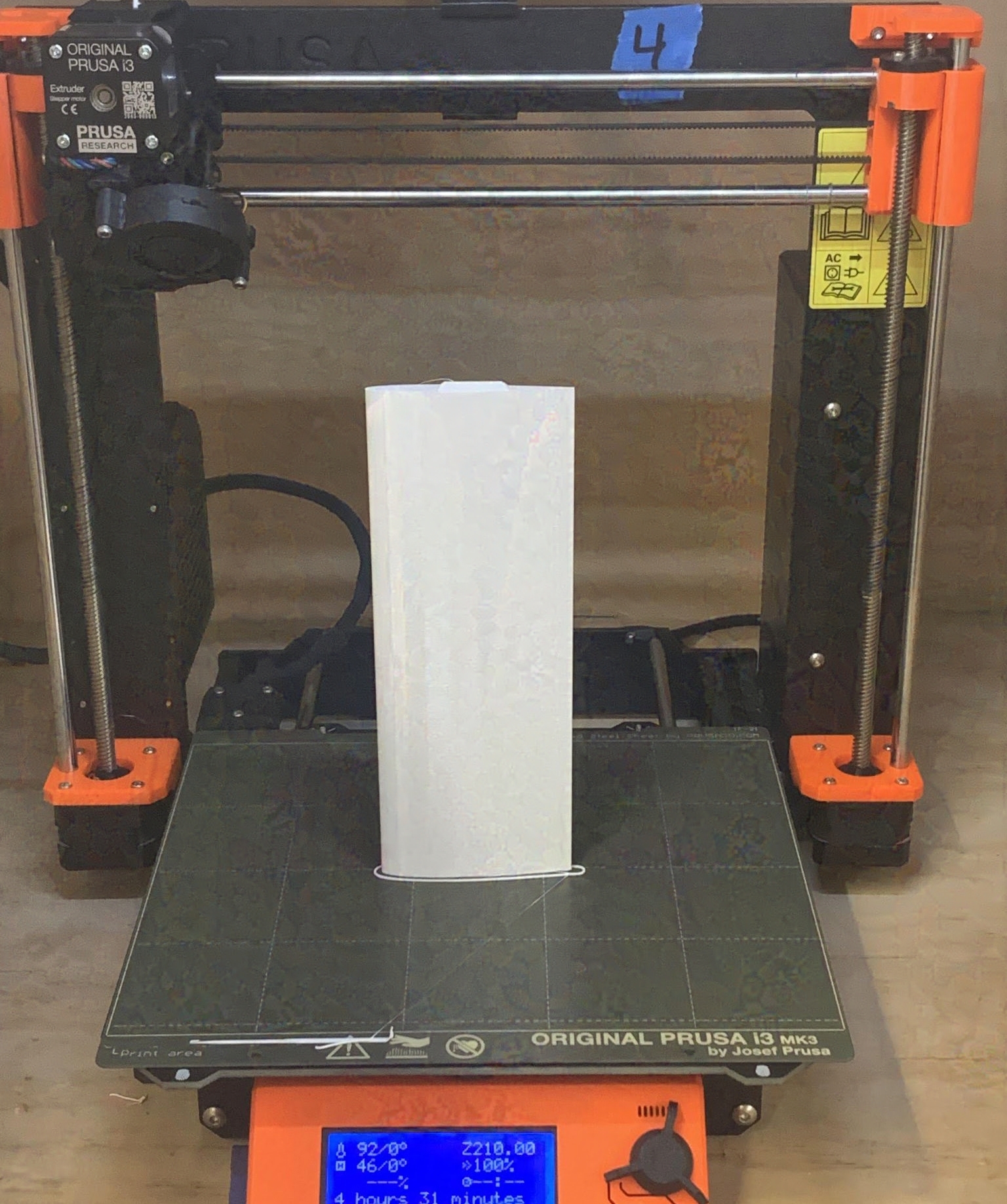
After 3d printing the individual pieces I used a slot in a piece of aluminum extrusion to align the pieces. My 3d printed pieces also had tapered aligning features that kept the piece straight. The length of 3d printed core was printed on several Prusa mk3 printers (white green and blue PLA) and the blade pivot point was printed on a mark forge printer with continuous carbon fiber reinforced nylon in several layers. The blade pivot is a critical part of the blade as it takes bears a predicted centrifugal load of around 4500 lbf when spinning at my maximum load case of 3000 rpm.
The yellow paper was used to determine the size and shape of the carbon fiber and supporting bags required to vacuum bag this layup. Below is a picture of the layup materials:
Layup
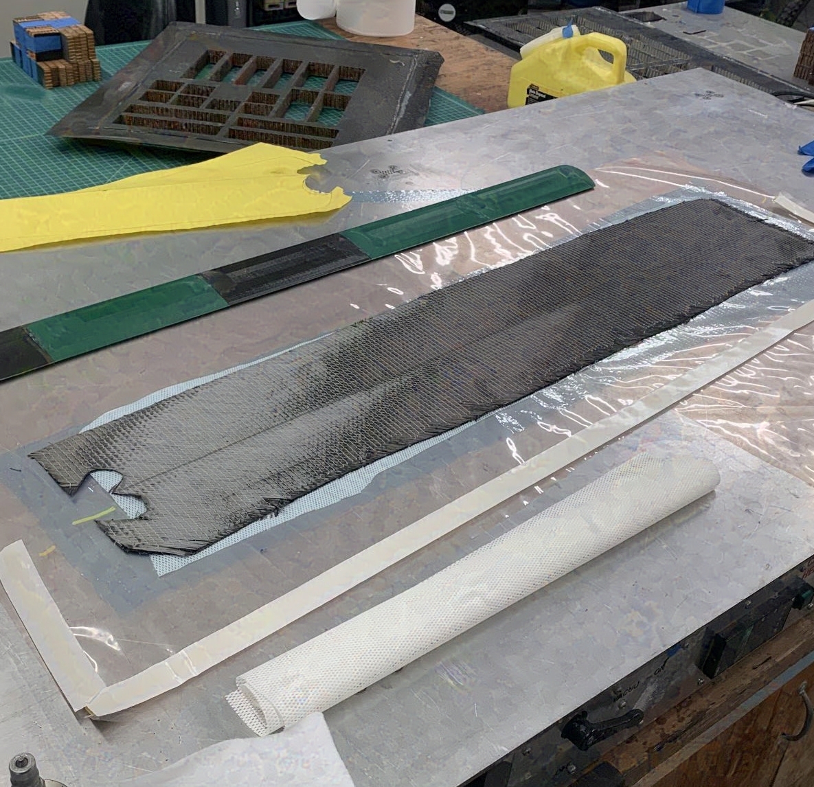
Vacuum Bag with tape to compress the layup to the mold and apply pressure.
Blue breather film to ensure surface finish and let air pass through.
White breather cloth to ensure a vacuum is pulled throughout the bag.
I used a 45/-45 single ply carbon fiber cloth and a fiber to resin ratio of 60:40. The fiber direction was 45 degrees offset from the span-wise direction of the wing to ensure maximum torsional rigidity. If I had use a 0/90 fiber layer with parallel fiber, the wing may have been too flexible and lead to fluttering at high rpm.
Pull Vacuum
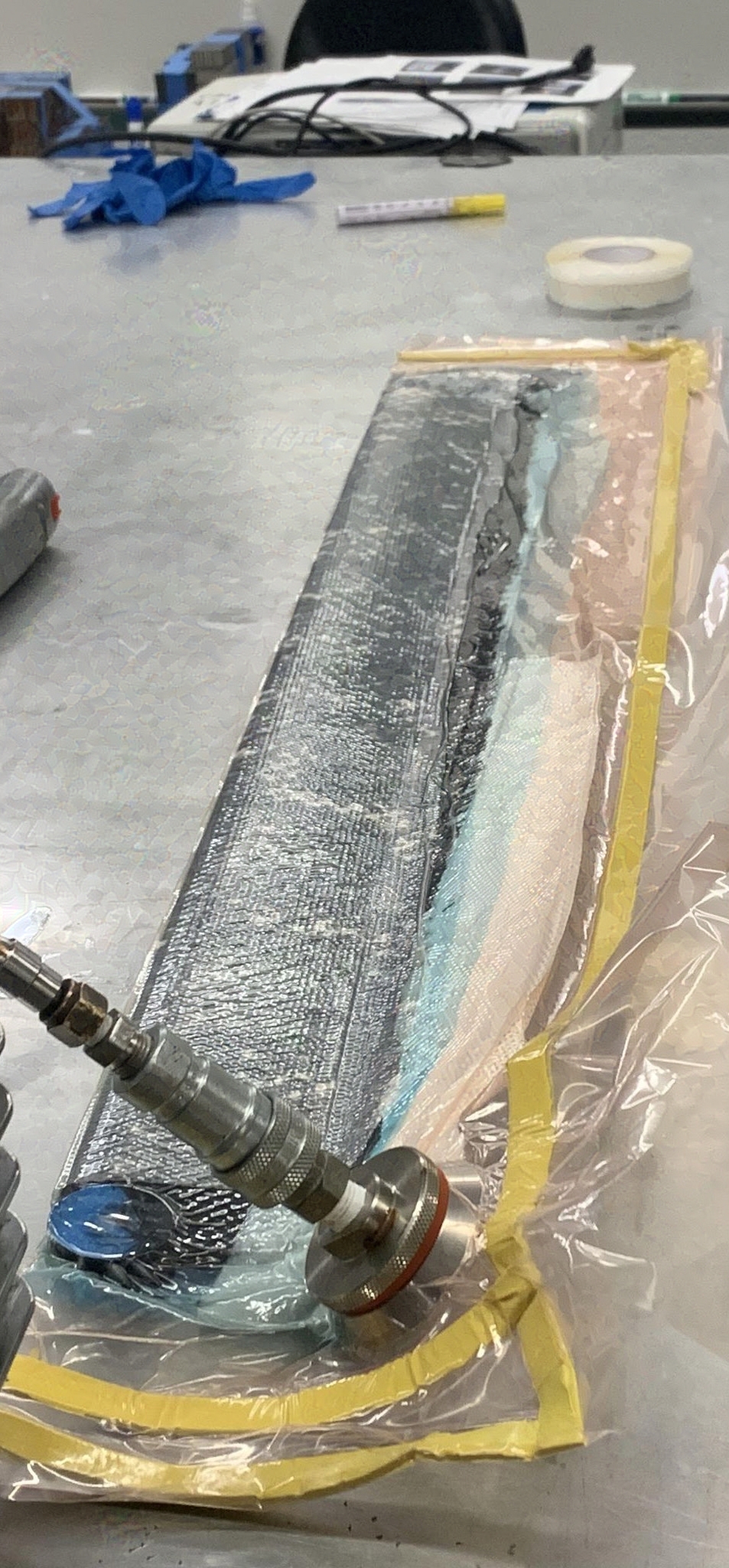
After I applied my resin to the carbon I placed the 3d printed core onto one side of the layup and folded the other half over the top. I added a vacuum port and connected it to a vacuum for 3 hours while the resin cured.
Finishing Coat
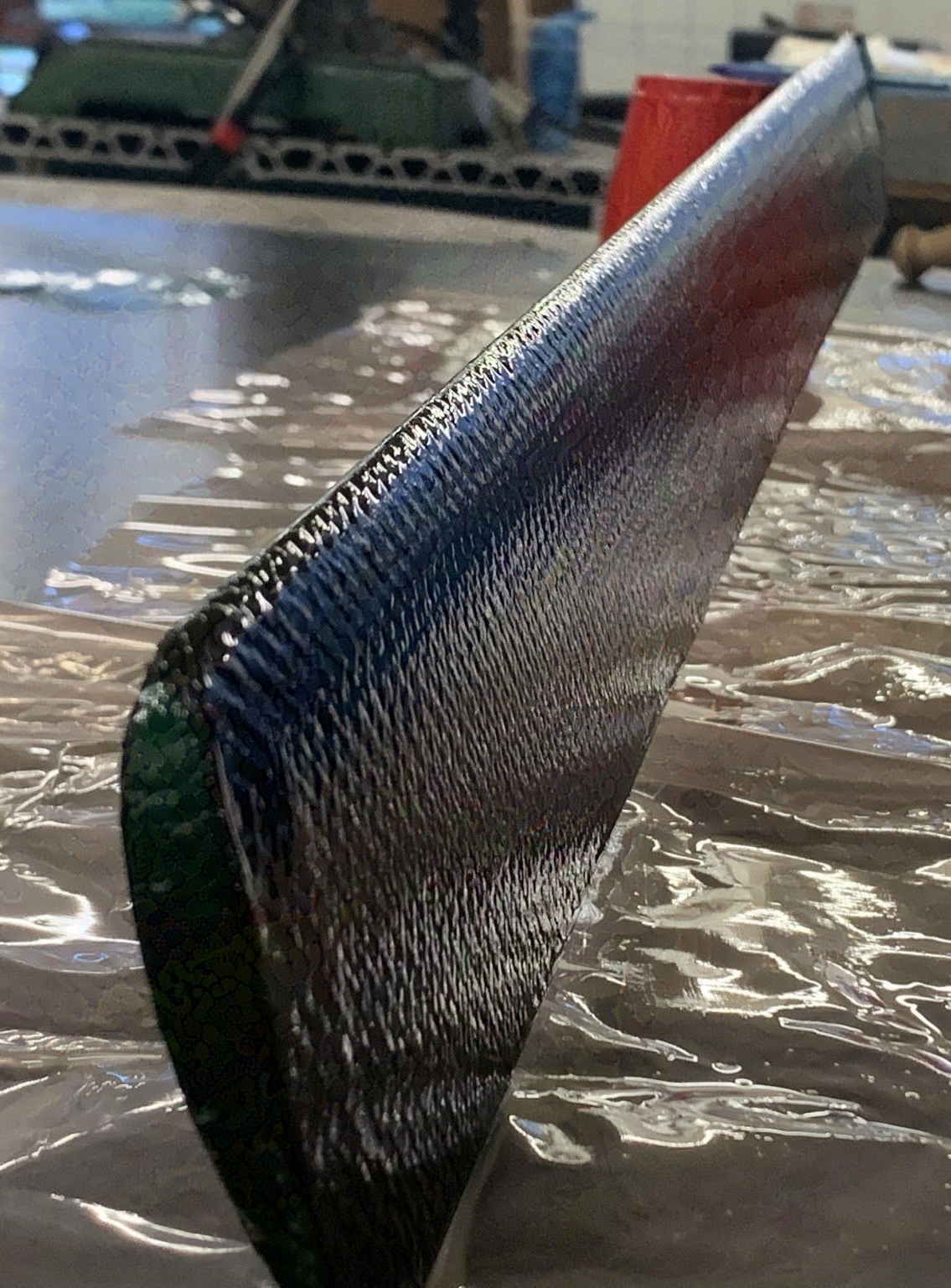
After taking it out of the bag i sanded it smooth and trimmed any loose edges.
Next I added a second coat of resin that was cut with about 15% acetone to add a smooth coating.
First and Second Blades
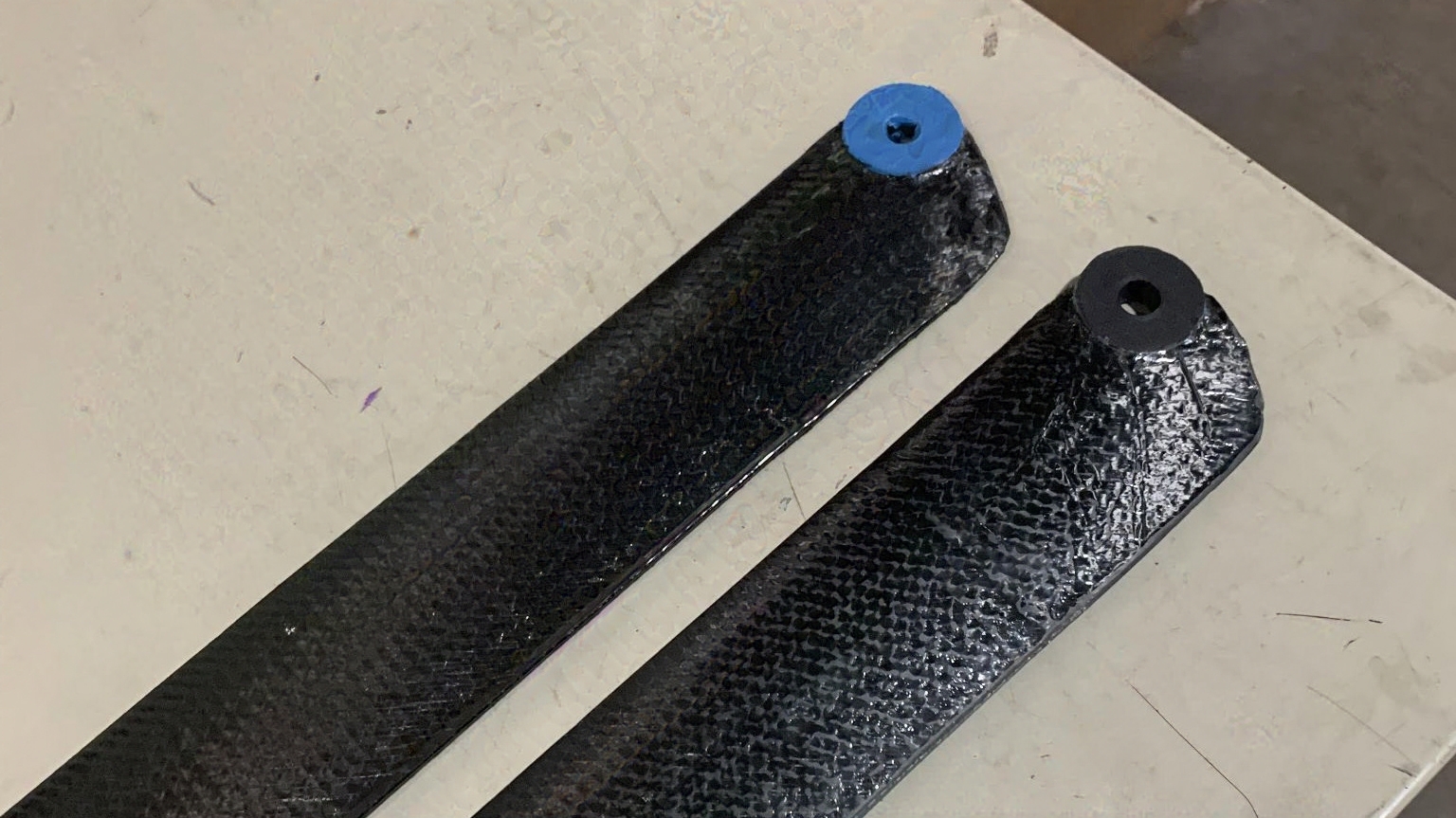
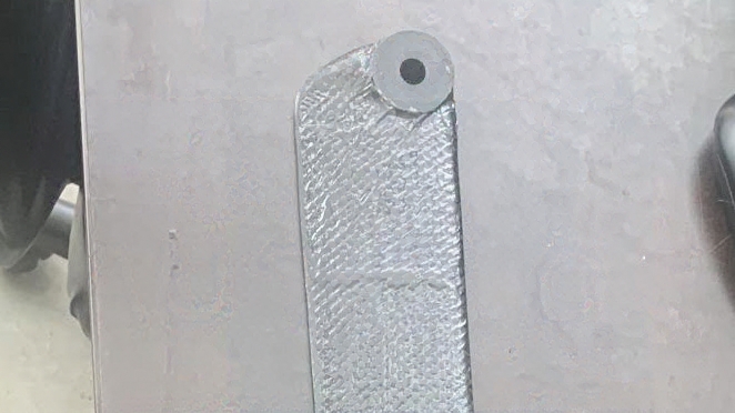
Unfinished [left], finished [right]
Finishing Thoughts
Overall the blades turned out pretty good. The weight of the blades are both 0.69 +/- 0.01 pounds which I was particularly happy with because I didn't have to do any balancing to try to match the blade weights. The surface finish of both blades has a minor imprinted surface texture of the underlying carbon fiber. One way I can think to remedy this is by using a higher resin to fiber ratio and by being more consistent with my resin application. For my current blades I will add some kind of sand-able primer and finishing paint with the hopes of reducing drag and surface friction. An area of concern I have is the strength of the carbon fiber reinforced nylon blade bases. I am looking into adding some kind of bonded metal plate or insert to increase the strength of the pivot point when it is in contact with the pivoting rod.